R-6464 Auralux Installation Guide
From our Skyline Collection, the R-6464 Auralux merges style with technology to provide a removable barrier and ambient lighting. The integrated LED system, featuring eight color options, enhances any landscape or exterior space. Made of durable 316 grade stainless steel for corrosion resistance, it maintains its finish in diverse conditions. Its design includes internal locking for easy access to restricted areas and elevated key-access to prevent debris accumulation, balancing accessibility with security.
PARTS LIST
|
# |
PART |
QTY |
|---|---|---|
|
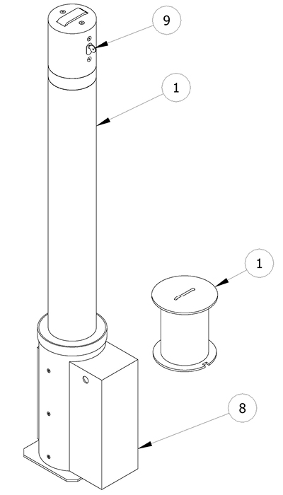
1 |
R6464 Auralux Bollard |
1 |
|
2 |
R6464 Auralux Receiver |
1 |
|
3 |
Removable Bollard Receiver Cover |
1 |
|
4 |
Key |
1 |
INSTALLATION EQUIPMENT
|
Auger |
|
|
Dirt Tamper |
|
|
Level |
|
|
Chalk/Marker |
|
|
Measuring Tape |
NOTE
- Always ensure any applicable site and safety codes have been followed.
- Electrical products should always be installed by a qualified individual.
- Ensure the power supply is protected by a breaker. Reliance Foundry recommends use of a surge protector.
- Do not remove or work on the bollard while live power is active. Always turn off the power supply to the bollard before removal.
- To protect the finish, keep bollards in original packaging until the moment of installation.
- Handle with care to avoid scratching or damaging bollard surfaces.
- Once scratched, bollards cannot be repaired to original form.
- Handle bollards carefully to avoid pinching fingers or other body parts during installation and operation.
Before installation
Study the site plans
Site plans are generally created by the architect of the project.
The architect will mark the intended location of each bollard on the plan.
Ensure that the plan coincides with the site and familiarize yourself with the intended arrangement of the bollards.
Check for hazards
Always check for hazards such as water pipes, gas lines, and underground wiring before digging. All applicable site and safety codes should be followed.
Prepare the site
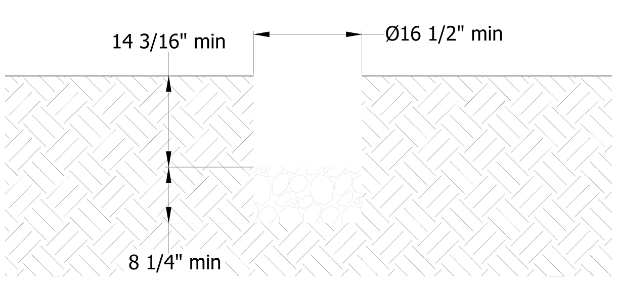
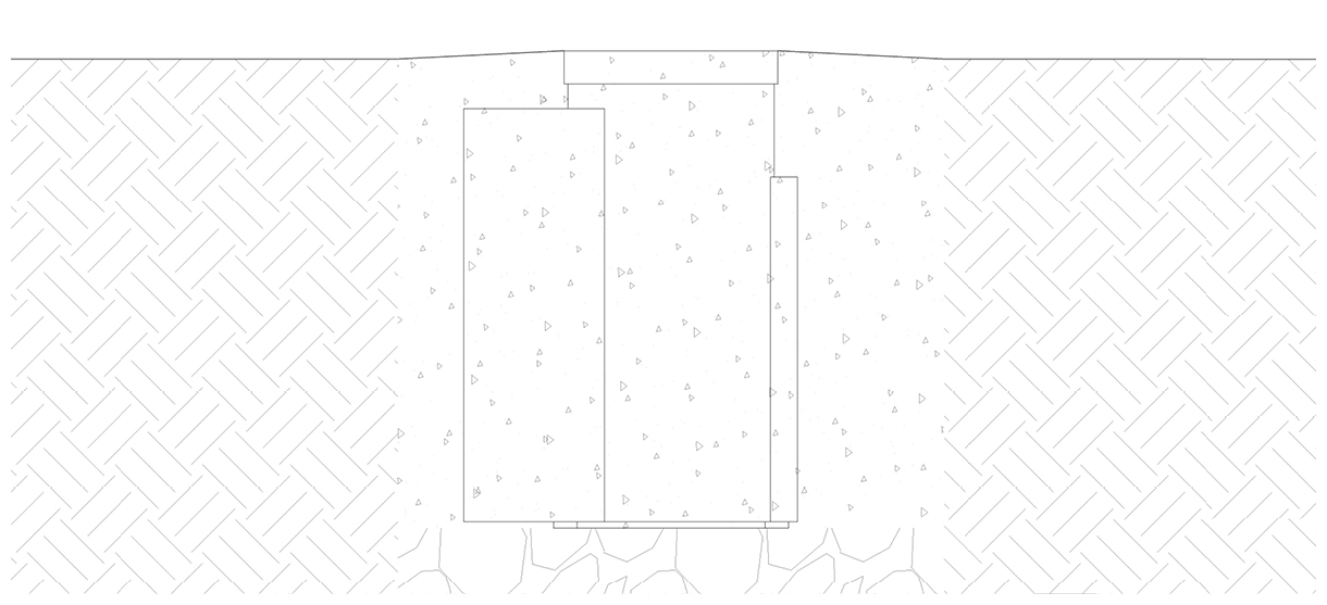
Please consult your local Building Code Department to determine the recommended digging depth below the frost line in your area. Choose this or 14-3/16", whichever is greater. Then add a minimum of 8-1/4" for holding the drain rock. This is your total digging depth.
The diameter of the hole should extend to a minimum of 16-1/2".
Note: If the recommended digging depth below the frost line is greater than the depth of the receiver, be sure to provide adequate drainage by piping through the concrete and connecting to the drain rock layer underneath.
Dig the site and prepare wiring route
Center the auger on the installation mark and bore a hole to the required depth and diameter.
Ensure the area is properly formed to create a perimeter that will hold wet concrete.
Use a dirt tamper to compact the soil below the intended surface.
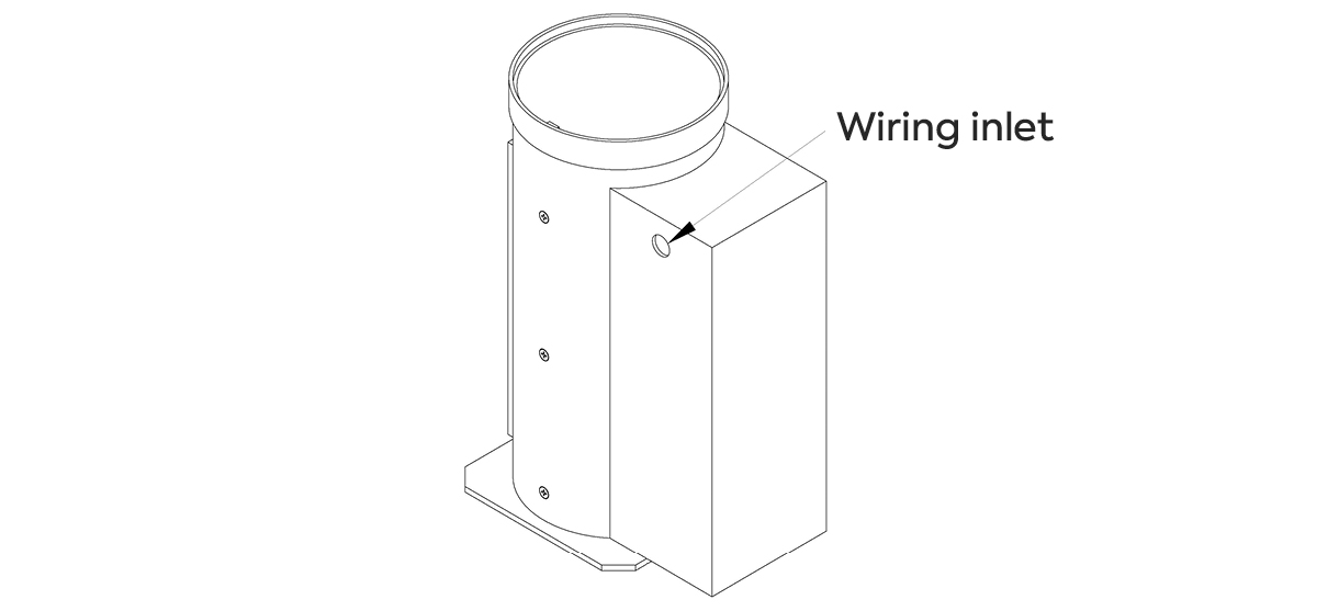
Note the location of the wiring inlet hole on the receiver and prepare site connection to meet hole once receiver is installed.
Add the drain rock
Add the drain rock to the installation site.
Prepare the receiver for designated location
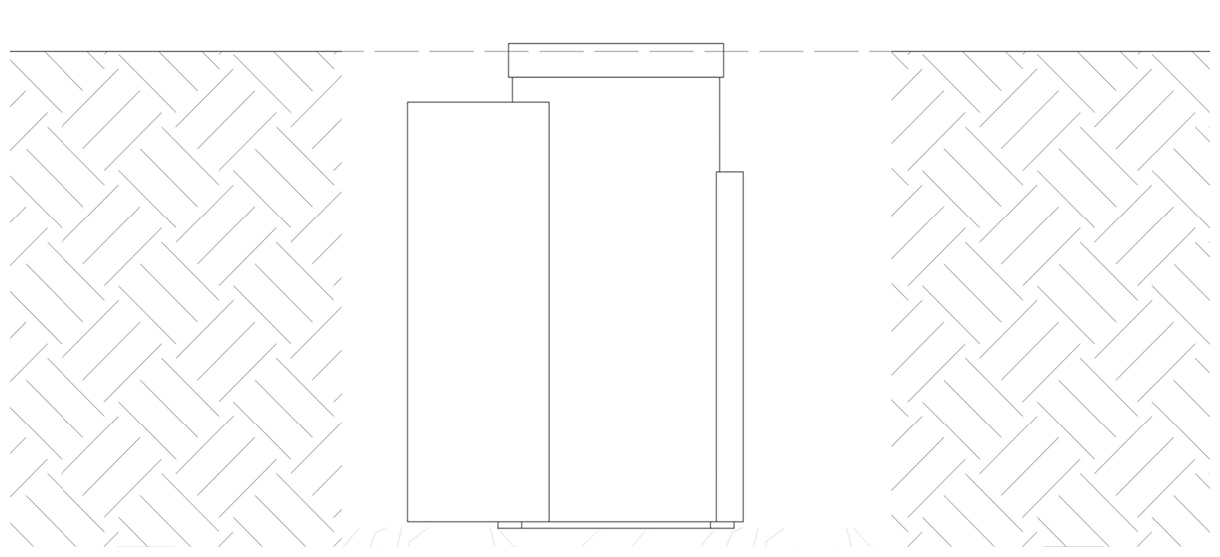
Place the receiver in the designated location and ensure that the top edge of the receiver is slightly above surface grade in order to create a slight berm.
Electrical Connection
Route Wiring and Connect Power
Before doing any electrical work, ensure the power supply has been shut off. Electrical connections should only be done by qualified professionals.
Route wiring to the wiring inlet hole on the receiver. Ensure wiring is suitably protected for burial in concrete. Use an appropriate conduit fitting at the receiver to protect the inside of the receiver.
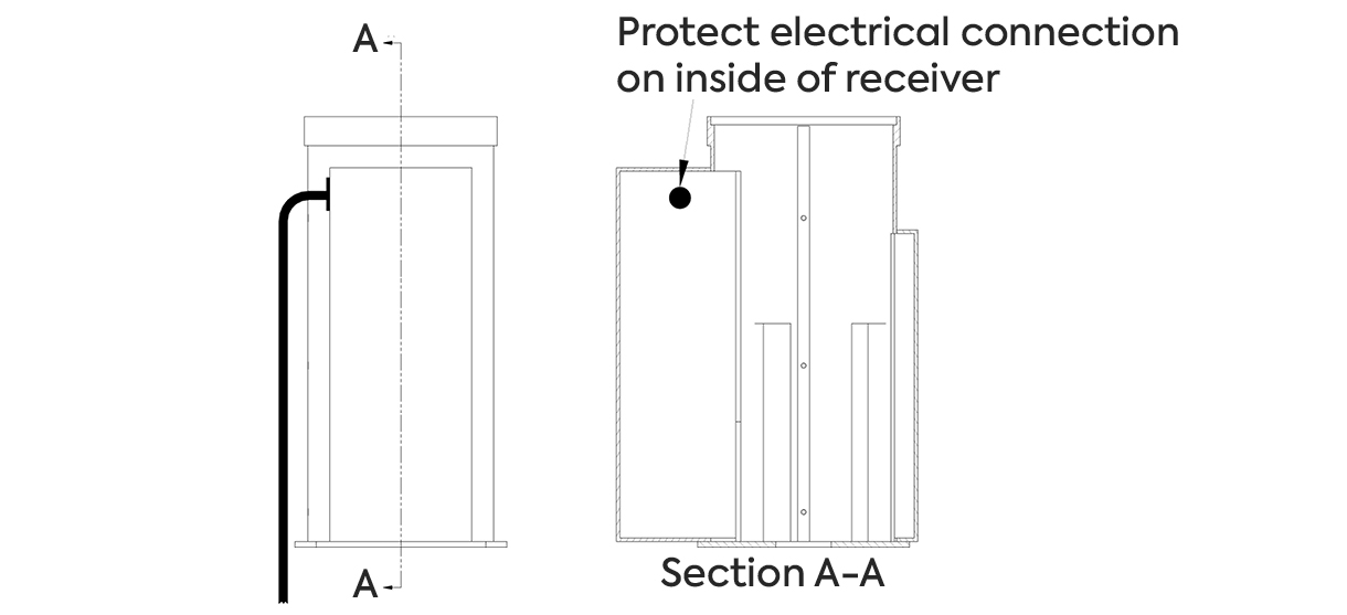
Note that the bollard is designed to drain any water that pools in the receiver, however, for safety reasons it should be assumed that the receiver will completely fill with water. It is recommended that the electrical wiring or conduit should be caulked or otherwise protected inside the receiver to prevent water from going back through the site connection. Duct seal putty, expanding foam, or silicone caulking are common for this task.
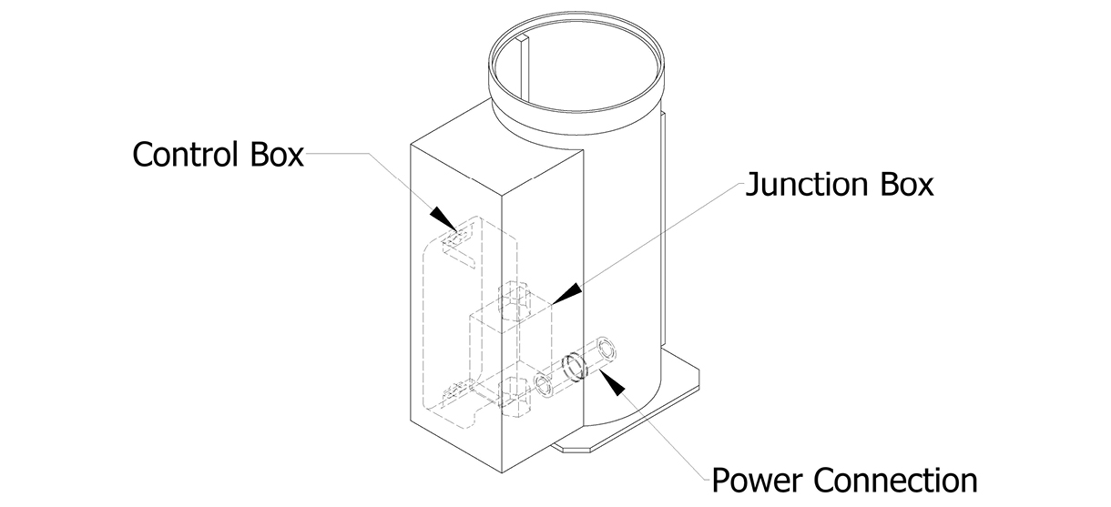
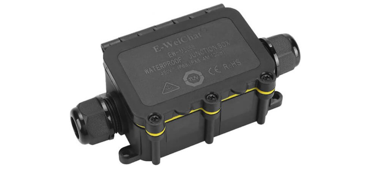
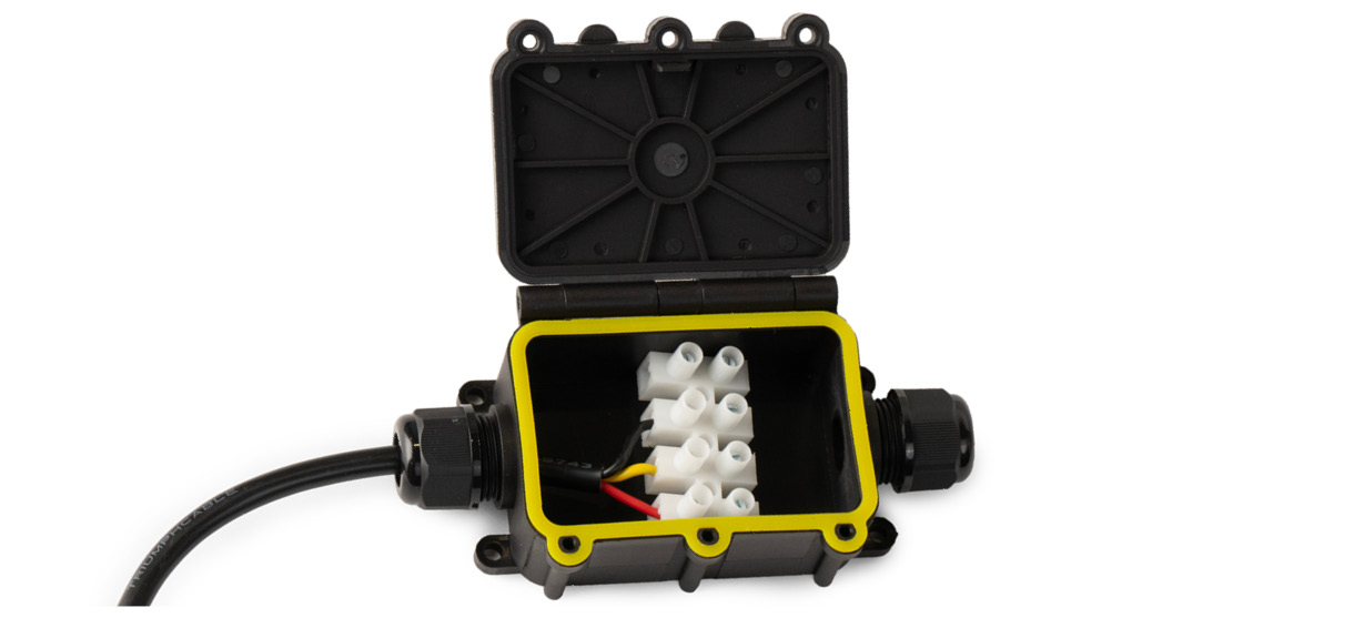
Locate the junction box inside the receiver. Bring the site connection to the inside of the junction box through the wire gland and connect as shown:
- L / Positive to red
- N / Negative to Black
- Ground to yellow
Ensure the box is properly closed before placing it back inside the receiver.
Pour the concrete
Mix and pour the concrete
Note: If the recommended digging depth below the frost line is greater than the depth of the receiver, be sure to provide adequate drainage by piping through the concrete and connecting to the drain rock layer underneath.
Ensure that the proper ratio of water and concrete mix is used—the concrete should have a similar texture to moldable clay.
Ensure the power connection inside the receiver has its cover installed.
Take care to pour the concrete evenly, ensuring the surface is level.
The concrete should be slightly raised up towards the top edge of the receiver to create a slight berm.
Allow the concrete to cure
A minimum of 2–3 days should be given for concrete to cure before beginning construction projects on new concrete surfaces.
*Note that moisture in the environment and cool temperatures can significantly slow the process
Secure the bollard
Prepare the bollard
Ensure the concrete has cured.
Keep the bollard in its protective packaging. Carefully set the bollard near the installation site.
When ready to install, remove the protective packaging.
Connect and set the bollard into the receiver
Undo the cover on the power connector in the receiver and connect the bollard’s power cable to the power connector.
Turn the key on the bollard to retract the plunger and lower the bollard into the receiver.
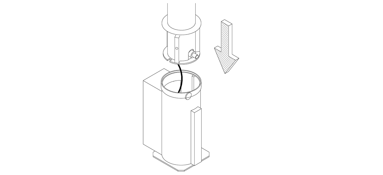
After setting the bollard, release and remove the key.
Inspect
Inspect the installation
Examine the plane of view from a distance.
Ensure the bollard is plumb to the surface, and the surface is flat.
Check the bollard for any signs of surface damage
For damage repair or other servicing needs, please contact Reliance Foundry’s sales department.
Check the operation
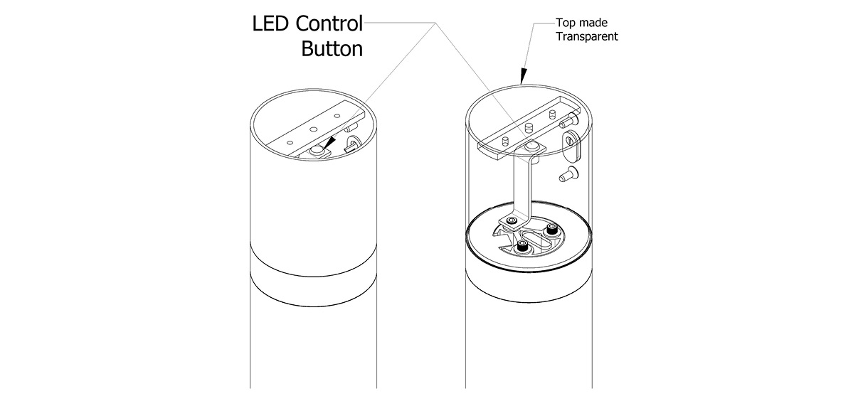
Turn the on the power to the bollard and ensure the light turns on. Remove the cap on top of the bollard and confirm the button inside changes the color of the light when pressed.
Note: if the light fails to turn on, try turning off the power source and turning it back on. Connecting the bollard to the receiver power while the power source is on can cause the light to fail to turn on initially.
Care and maintenance
Reliance Foundry manufactures its products to the highest design standards to ensure their durability. Reliance Foundry’s bollards are finished with long-lasting powder coating. In most North American environments, routine inspections and cleaning will ensure that bollards retain their aesthetic appeal. Proper care and maintenance are required to maintain the finish and ensure a full service life.
Operating Instructions
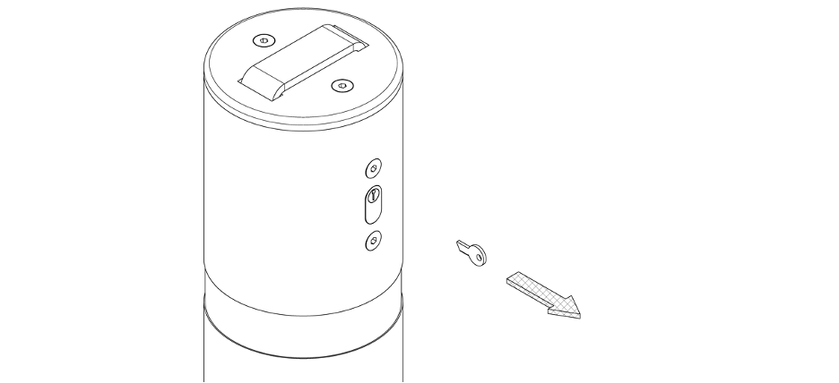
Removing the bollard
Before removing the bollard, turn off the power source to the bollard. Do not remove or work on the bollard with live power.
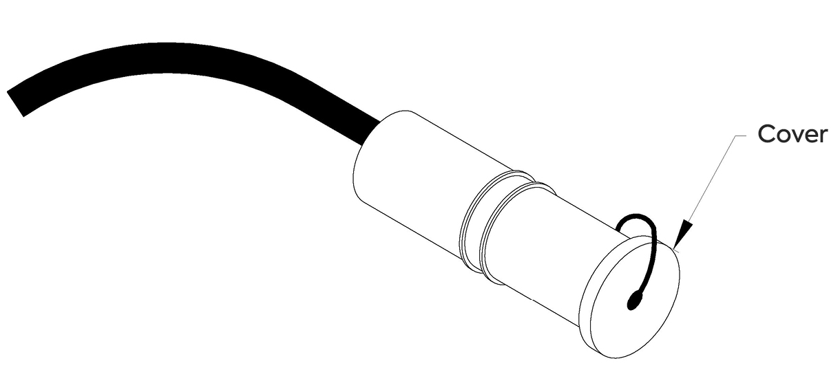
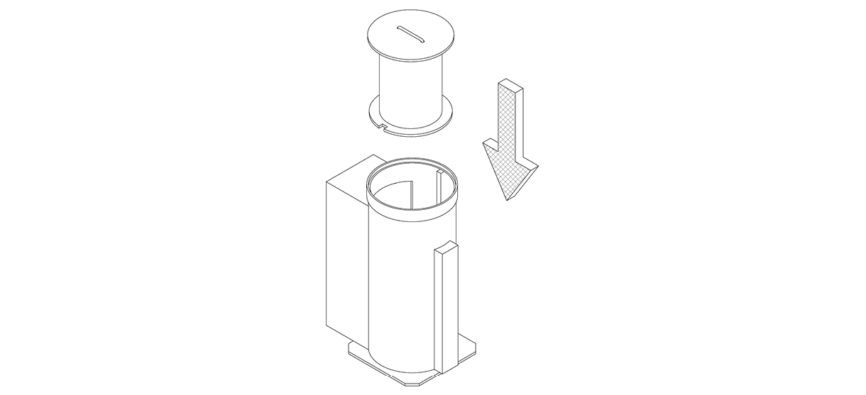
To remove the bollard, insert the key and turn to retract the plunger inside the receiver. Carefully pull the bollard out of the ground, taking care not to move it too far away from the receiver (the bollard will still be connected by its power cord to the receiver). If needed, lay the bollard down carefully on the ground next to the receiver. Disconnect the power by unscrewing the blue collar in the middle of the power connector. Screw the connector cover onto the receiver side of the connector. The connector cover should always be placed over the connector when the bollard is removed. Place the receiver wires neatly in the bottom of the receiver and place the receiver cover inside the receiver. The receiver cover should always be installed when the bollard is removed.
To put the bollard back, repeat the above instructions in reverse:
- Remove the receiver cover
- Twist off the power connector cover
- Connect the bollard side of the power connector
- Place the wires neatly in the bottom of the receiver
- Turn the key on the bollard to retract the plunger
- Lower the bollard into the receiver
- Turn the power to the bollard back on
Changing the Color
Remove the cap to the bollard using the provided security allen key. Press the metal button inside the top of the bollard.