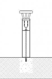
Installing Solar Bollards using Concrete Inserts
Reliance Foundry solar bollards can be installed in existing concrete with drop-in concrete inserts. Drop-in concrete insert installation is recommended for decorative applications and for creating architectural perimeters.
It is important to note that with this installation method, the lighting bollard will offer little impact resistance. The function of the bollard is primarily for lighting, and architectural or landscape highlighting. Solar bollards are self-contained devices and require minimal ongoing maintenance.
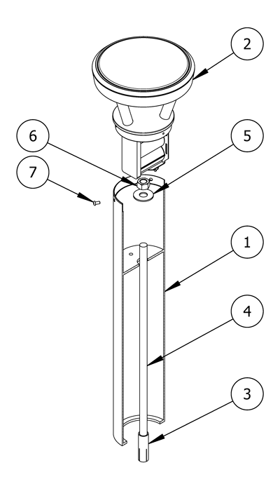
PARTS LIST
|
# |
PART |
QTY |
|---|---|---|
|
1 |
Bollard Base |
1 |
|
2 |
Bollard Solar Light Cap |
1 |
|
3 |
3/4″ Drop-In Concrete Insert |
1 |
|
4 |
3/4″ Threaded Rod |
1 |
|
5 |
3/4″ Washer |
1 |
|
6 |
3/4″ Hex Nut |
1 |
|
7 |
Hexagon Socket Button Head Cap Bolt |
3 |
INSTALLATION EQUIPMENT
|
1″ Masonry Drill Bit |
3/4″ Insert Setting Tool (or equivalent) |
|
1-1/8″ Socket Wrench |
Special Hex Key |
|
Broom/Pressure Washer |
Measuring Tape |
|
Vacuum |
Chalk |
|
Hammer |
Hammer Drill or Rotary Hammer |
|
Level |
|
NOTE
- To protect the finish, keep bollards in original packaging until the exact moment of installation.
- Handle with care to avoid scratching or damaging bollard surfaces as abrasions will lead to rust.
- Once scratched, bollards cannot be repaired to original form without re-finishing the entire surface.
Before installation
Check for hazards
Always check for hazards such as water pipes, gas lines, and underground wiring before drilling.
Clean the surface
Dirt and debris can affect the line of sight and disrupt placement of the bollards.
Use a broom or pressure washer to clean the concrete surface prior to bollard installation.
Study the site plans
Site plans are generally created by the architect of the project.
Refer to site plans to locate and mark the precise center point of each bollard.
For secure installation, ensure there is a minimum radius(1) of solid oncrete around each mark.
Drill the hole
Create pilot hole
Tap a pilot divot hole in the center of each mark.
This will prevent the hammer drill or rotary hammer from drifting while boring the hole.
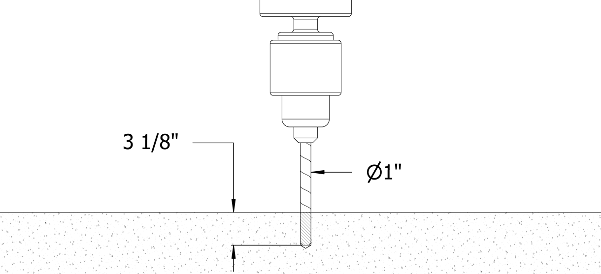
Set the depth control on the hammer drill (or rotary hammer) to 3-1/8″
If depth control is not available, mark 3-1/8″ on the masonry bit.
Drill the hole
Drill a hole that has a 1″ diameter and 3-1/8″ depth.
Drill on high speed, using the hammer function if available.
Check the masonry bit often to ensure it remains free of debris.
Secure the bollard
Clear the hole
Clear the hole of all debris and/or standing water using the vacuum.
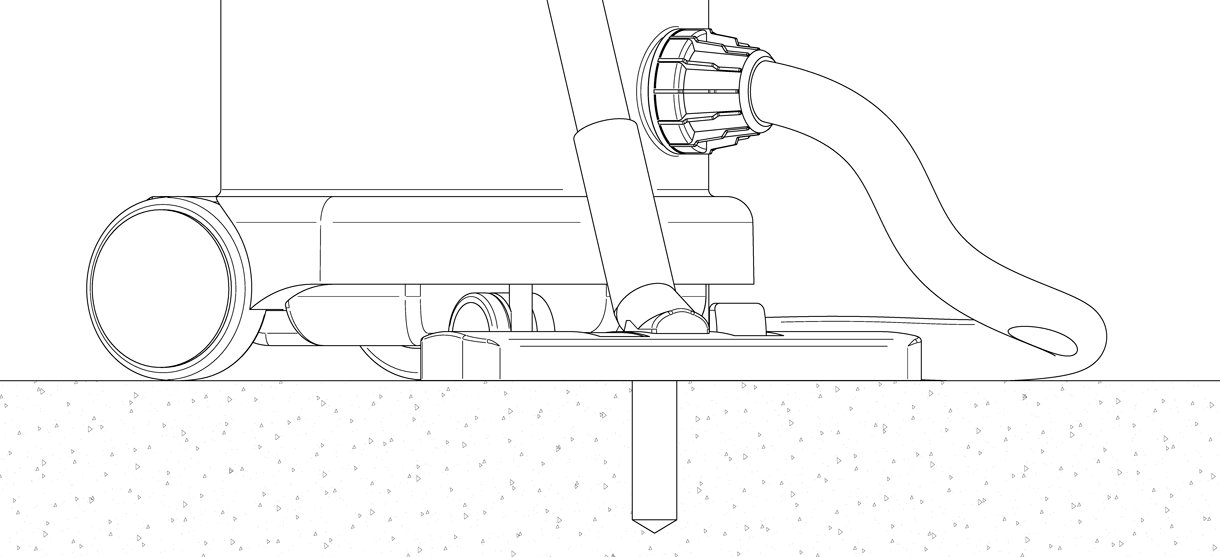
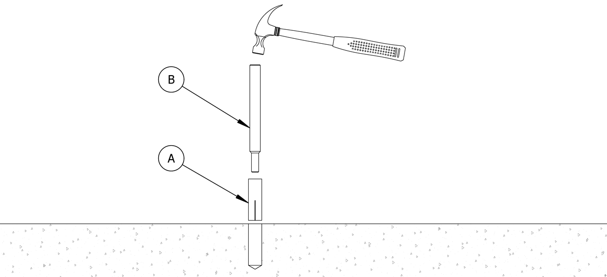
Tap the drop-in insert into the hole
With the slotted end facing down, drive the drop-in insert (A) down until its top sits flush with the concrete surface.
Ensure that the top is perfectly level.
Set the concrete insert
Insert a setting tool (B) into the threaded hole, then hammer down.
If a proper setting tool is not available, an equivalent flat-end punch can be used.
This will cause the internal expansion plug to set the concrete insert in place.
Place the bollard base near the concrete insert
Keep the bollard in its protective packaging. Carefully place the bollard base near the installation position.
When ready to install, remove the protective packaging.
Set the bollard over the concrete insert
Set the bollard base upright and maneuver it so the center lines up with the threaded hole in the concrete insert.
Lower the threaded rod and tighten
Lower the threaded rod through the bollard’s shaft.
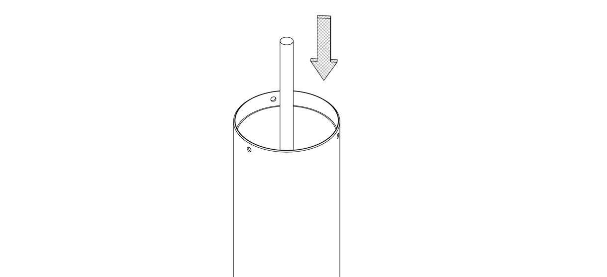
Continue to thread the rod into the concrete insert.
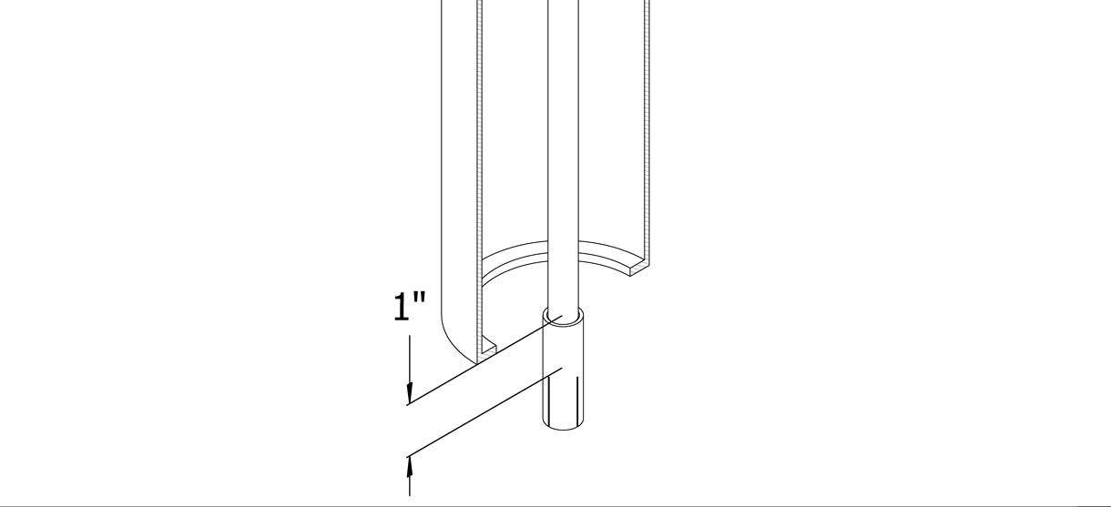
Tighten(2) the threaded rod by hand until it is secure in the concrete insert.
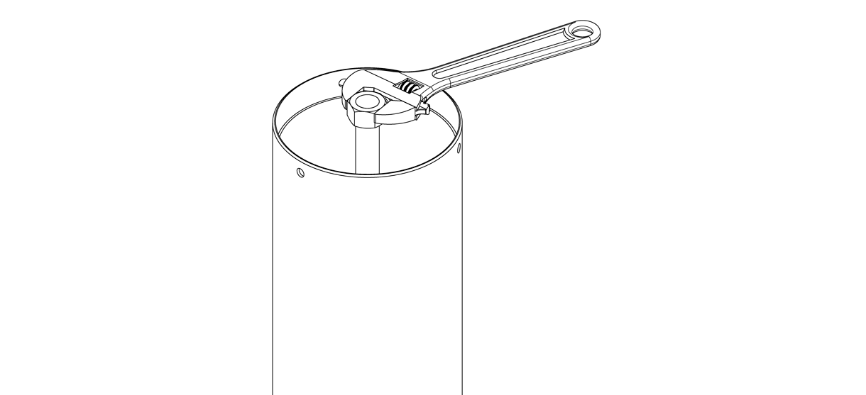
Secure the bollard
Place the washer over the threaded rod so that it rests on top of the bollard.
Apply the 3/4″ hex nut to the threaded rod and tighten with a socket wrench until the bollard is secure.
Install the solar light cap
Connect the battery
With the lighting assembly still in its packaging, locate the battery’s wire plug and connect to the 2-pin socket attached to the light fixture.
Once connected, the lighting fixture will run a test pattern and flash for 3–5 seconds.
Note: If the light does not flash, please stop installation and contact Reliance Foundry’s sales department for assistance.
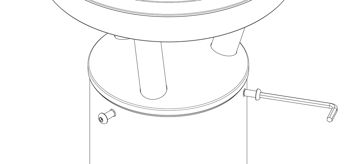
Secure the solar light cap
Remove solar light cap from its packaging.
Place the solar light cap on top of the shaft of the bollard.
Secure the solar light cap to the bollard base with the three bolts and tighten equally.
Note: For asymmetrical lighting, consider the lighting pattern. When attaching the solar light cap, twist it to the desired lighting pattern before bolting down.
Inspect
Inspect the installation
From a distance, examine the plane of view.
Ensure the bollard is plumb to the surface, and the surface is flat.
Check the bollard for any signs of surface damage
Abrasions should be covered as soon as possible to prevent rust and ensure the proper life of the bollard. For damage repair or other servicing needs, please contact Reliance Foundry’s sales department.
Care and maintenance
Reliance Foundry manufactures its products to the highest design standards to ensure their durability. Reliance Foundry’s bollards are finished with long-lasting powder coating. In most North American environments, routine inspections and cleaning will ensure that bollards retain their aesthetic appeal. Proper care and maintenance are required to maintain the finish and ensure a full service life.
1. Concrete insert manufacturers such as www.ucanfast.com recommend an anchor spacing of 7-1/2″, and a minimum edge distance of 9″ for 100% performance.
2. The manufacturer recommends tightening the threaded rod to a depth of approximately 1″ into the concrete insert.